Pilot ACE - Quick Start Tutorial
This is a quick start tutorial for the Virtual Pilot ACE simulation. It will help you to get started using one of the first general-purpose, stored-program computers to be built in the United Kingdom. The console and most of the computer layout as shown are actually the latest implementation as it was by the end of it's life in 1956. I have though, taken the liberty of adding back the DSIR / NPL display banner from the photos of the original in 1950!

Moving around the simulation
The website can be viewed from a smaller mobile device, but to be able to use it properly, this really needs a larger screen, keyboard, and mouse, so we’re assuming that you’re viewing this from a PC or Mac.
There are two modes which can be switched between by using the mouse button. The current mode is shown in the bottom left of the screen: a Use mode which is indicated by a pointing finger icon and a View mode which is indicated with an eye icon.
If in View mode, just click the mouse button to switch to Use mode. If you’re in Use mode, click with your cursor anywhere where there isn’t a control (the background is a good choice!) to switch back to View mode.
View Mode
In this mode, move the mouse to look around your environment and to look at specific controls you want to access. You can move around the area by using the W,A,S and D keys to move forward, left, back, and right respectively. Try walking around to look at the computer.
Use Mode
In this mode, when you are close enough to the console, a cursor will be available on screen and allow you to click on some of the switches, dials, and buttons to control the computer.
Other Controls
Shift : The shift key can be used in either mode. This lowers or raises your point of view, the difference between crouching/sitting and standing for example.
If you find that the simulation is running a little slow on your PC / Mac, there are some options in the top right to remove some of the visual items on screen. Try hiding the Hollerith machine and the Computer itself which should make rendering a little better.
The cathode-ray tube used for output had a viewing cover to make it easier to see the display in a bright room. If you'd prefer to see this directly without the cover in the way, just check the Hide Display Hood option
Loading your first program
The first program ever run on the Pilot ACE on 10th May 1950 was called Successive Digits so let's attempt to run that now. Make sure you are in directly in front of the console and can see all of the controls. The button in the top left marked "View Console" should take you directly to face the console if you get lost (or want to get there quickly!)

A list of the programs, which would have been on packs of punched cards, can be accessed using the button marked "Load Punched Cards" in the top left of the screen.
Scroll down the list of available programs until you find SUCDIGS. The description gives a little information about what it does (more information and a full breakdown of this program is available on the software page). Click this program to load the punched cards into the Hollerith read hopper.
A clipboard will appear giving you basic operating instructions on loading and running the program, you can close these using the X button in the top right if they get in the way.
If you haven't already, click the check box option in the top right to "Hide Display Hood". This will remove the cover from the cathode-ray display so you can see it easier!
To begin, and tell the Pilot ACE to start loading the punched cards, there was a switch called "Initial Input" which cleared down the delay lines and called the reader to start loading cards. Note: This switch was, I believe, on the card reader itself, but I have placed it on the console itself to make it simpler for you to operate on the simulation.
To use a switch on the console, hover your mouse over the Initial Input switch (you should see the cursor change to a hand icon) then click and drag down (or up) to change the position of the switch. Note that some switches are spring-release and will return to their initial position when you let go, others will stay in the position set.
Press the "Initial Input" switch down once to start the punched cards loading into the computer
If you watch the display in the top left, this defaults to showing the contents of Delay Line 1. You should see the program load into the delay line where it will show as around 10 lines of dots. Each line is a single instruction for the computer.
The first command of the program is a "stopper" which means the computer is waiting for input and to be told to continue with the next instruction. The expected input for this program is to set one of the "Input Dynamiciser" switches to set a value for the computer to add. The program is basically going to add this value over and over again until it overruns the memory on the delay line it's counting on. When this happens, it will add a light on the "Output Staticiser" and start again. Once all 32 of the lights are lit on the Output bulbs, the program will return to the start and await another number.

The number we choose is a binary value, but in reverse binary. This means that if we wanted to enter the value 1, we would just set the grey switch on the far left down. But the Pilot ACE can count pretty high, so waiting for it to add 1 over and over again will take a while, so let's choose a switch (and therefore a binary value) much higher.
Press down on the grey switch on the Input Dynamiciser which is under the value 25. (it's the 8th from the right)
If all has gone well so far, you should see a light has illuminated next to the 25 showing we've set a value for the input. Now let's start it running.
Press down on the red switch marked "One Shot"
The One Shot switch sends one signal to the computer to continue running the program, if you watch, the Output Staticiser lights will illuminate one at a time from left to right over about 5 seconds of time. Well done - you've just run the first program that was run in 1950 and your Pilot ACE is functioning normally!
The program has returned to the start, so you can repeat this program again with a different input number if you like to see what happens. First, we need to clear the current value in the Input Staticiser and to clear the bulbs of the output. To do this, press down once on the "Clear I.D" switch and also once on the "Clear O.P.S" switch shown
Press down on the Clear I.D switch to clear the input, then on the Clear O.P.S switch to clear the output lights.
Now, choose a different value to start adding. If you choose a higher switch (26 upwards), then the lights will illuminate faster. If you choose a lower one (I wouldn't suggest you choose much less than 20), it will take much longer to light each bulb. Start the computer again with the One Shot switch.
Let's take a look at the computer actually counting. Set the Input to be the 20 light and start it running, each bulb should start to light up with about a 10 second delay.
We can change what is shown on the display to see some of the other delay lines by using the five grey switches under the tube display. The switches set the Delay Line to show (in reverse binary), so to view D.L 1 (as we have in the default), we just set down the first switch on the left. (10000 = 1). If we wanted to view Delay Line 5, then we would set 10100 = (1 + 4 = 5). There are 11 main long delay lines in total, but as the SUGDIGS program is quite small and only fills a part of the first delay line, most will currently be empty.
There is a special display though on setting 16 (this is the far right grey switch only 00001 = 16). Switch to that display now to see it (note you may want to restart the program adding up again if it's already finished by now).
Set the first grey switch under the display to the middle and the far right one down.
The display should now be showing a selection of some of the short delay lines, these are from top to bottom; DS12 (odd and even), DS14 (odd and even), TS15, TS16, TS20, TS26 and TS27. The value being added up is being stored in TS16. Once that's filled up each time, the display bulb is being shifted up in TS26 and then shown on the O.D, so it illuminates the next bulb each time.
Being able to see all of the memory and what is stored in it at any time is a very useful debugging tool. Historically though, it's difficult to find a description written down of exactly what the monitor was used for and how it was switched, but going by some of the programs we have and by instructions on the DEUCE computer that replaced this one, it's a good assumption that this is what it would have shown.
You can also see the instruction lights flickering as the computer runs each command in turn (centre of the console marked Next Instruction Source, Source, Destination and Serial)
Running Million Factors (Slow)
On 29th November 1950, the Pilot ACE was just about ready to show off to the world and members of the press were invited to see this new computer for themselves. "For the demonstration we had three main programs, two popular and one serious. Of the popular programs the first took a date in decimal from input keys and gave out the corresponding day of the week on a cathode-ray tube while the second took a six-figure decimal number and gave its highest factor. The serious program traced the path of rays through a complex set of lens; it was virtually impossible for anybody not intimately connected with the computer to know for certain whether this was working correctly." [WJ05 100]

Donald Davies, who was present at the demonstration in November 1950, later recalled that "The program took in a six figure decimal number and 'gave its highest factor'. Since the output allowed only numbers up to 999, I think it was actually the smallest factor. A bottle of beer was offered to the press for finding any six figure prime. Whenever a multiple of three or seven was called out, Wilkinson responded 'divisible by 3' or 'divisible by 7' before it was entered*. This amazed the press more than the machine itself." [DD2]
Unfortunately, the original code for these three programs are now lost to time, but we do have a version of the factors program written for the DEUCE computer which came later called ZV03 'Million Factors Slow'. "a demonstration programme [which] reads a number less than a million from the I.D., computes its smallest factor, if any, and displays this, or the word PRIME, in the scope". It is another very early program, DEUCE Program Number 7, so it was almost certainly derived from a similar Pilot ACE version.
While the DEUCE and Pilot ACE are similar in structure and both use Delay Lines for memory, the command list is very different, so you can't just run it directly. The Pilot ACE doesn't even have the hardware divide function of the DEUCE!
It has taken a lot of work, but I have managed to convert the ZV03 program back to work on the Pilot ACE which I release with this simulator, 75 years after it was run on the original Pilot ACE.
Stop any current program running (Press down the Stop switch) and you can also Clear all of the stores manually by pressing down the yellow "Clear Store" switch. If you're really having trouble, you can always restart the simulator.
Click Load Punched Cards and select "Million Factors Slow"
Press the "Initial Input" switch down once to start the punched cards loading into the computer. This will take a few seconds, it uses many of the delay lines this time.
We've seen that the Clear I.D. switch when pressed down clears the I.D value and springs back to it's mid position. But there is a different option on this switch! If you push it up (it will stay in this position), the I.D will be continuously cleared. This means we can use the I.D. to enter multiple single values without having to press the Clear I.D. switch each time. We'll use this feature on this program.
Press the Clear I.D switch UP
Next, we need to learn a little about the timing of the machine and the scope. When you load a program into the delay line, it will normally just load into whatever the current minor cycle the computer is currently running, not necessarily into 0! This means that if we're using the scope to show something as a display, it won't always be lined up centrally on the display. We need some way to adjust where the scope's top line is on the delay line.
To do this, there is an option called MC Slip which allows us to step the scope's initial line through the 32 minor cycles so it will show where we need it on screen. It's not specificed in any documentation I can find which switch was used to do this, but I have set this to be on the yellow switch below the scope itself.
We need to look at a delay line that has some data on it, and for this program, our delay line 10 is the most useful. We must switch to D.L.10 on the scope to see it, this means we need to put the grey switches below the scope to 01010 (2 + 8 = 10).
Set the 2nd and 4th grey display switches Down, all the other three to mid position
You should see the delay line with the numbers 0 - 9 shown as characters (these are used to draw to screen later on as our result!).
Press down on the yellow Mc Slip switch one at a time until the 5 - 9 digits are central on the scope display
Our output of the program is set to display on D.L.8, so we want to switch to that display now. You should have a blank screen shown.
Switch to D.L.8 which (if you're on D.L.10), means switching up the 2nd grey switch
Now, we want to start our program, which we do by sending a single-shot
Press the 'One Shot' switch down once
Now, we're going to enter a number for the computer to calculate either it's smallest factor, or if it's a prime number. We can enter any number from 2 to 999999
The way this program is set to read in the value is by using the P1 - P10 grey switches on the I.D. to be the digits 0-9. Note that the first switch on the left P1 is the digit ZERO, not 1, so to enter a 3, we need to press down switch 4! To enter an 8, it's switch 9 etc.
Alternatively, the documentation doesn't specify what the white number buttons below the scope are either - but I've set them to also be the input for this program! I have set each white button digit (0-9) to set the I.D to the correct value. Pressing the 0 white button for example will set P1 on the I.D, pressing 8 will set the P9 switch on the I.D etc. In this way, you can more easily set a value in the computer.
The computer is looping waiting for the I.D. to be NOT 0 and as soon as a switch is changed, it'll set the first digit and then (as the clear I.D is up) will clear the I.D ready for our next digit.
Let's try 1377 (which is divisible by 3) to see if it's working.
Either set the I.D. switches one at a time, press down P2, P4, P8 then P8. Alternatively, press the white buttons under the scope, 1,3 7 and 7.
If you enter a full 6 digit number, then the program will start calculating automatically. If you have less than 6 digits in your number, we need to tell the computer we're done. To do this, we use the P32 switch (the one on the far right of the I.D), or you can press the white button marked P32
Press the P32 button
This calculation will not take very long, just a second or so and the computer will display the digit of the smallest factor on screen. You should see the number 3!
We can repeat this for another number by pressing One Shot switch to get us back to the start
Press the 'One Shot' switch down once
Let's repeat this for another number, how about 743 which is a prime - will the computer be able to find the correct result for us!
Enter the number 743 and press P32
If you've entered it correctly, then the Pilot ACE should tell you it's a prime on screen!
Try this with a few different numbers, try 999997 for example which should take a little longer to calculate. Is it prime or what value do you get? If you want to repeat the test from 1950, then guess a 6 digit number and see if you can find a Prime number! If you find one, you'll have to make do with a Virtual Beer rather than the real one they would have given out at the press conference! It'll take a little while for it to calculate
While a longer calculation is running, why not try switching to display 16 (see instructions above) to see the computer working away in the background doing divisions over and over again trying to find the answer!
Running Bounce
Around 2010, David Green released a Windows emulator of the Pilot ACE and he (and his emulator) has been a huge help getting this simulation completed. He included with his emulator a program called Bounce. He says that "The program was written in 2011 and has no historical significance." but that "it is authentic Pilot ACE code".
This program can be found in the punched card list as "Bounce" and depicts a ball (in DL 8) bouncing within the confines of the monitor. It doesn't do any more than that, but I love it as a great demonstration of the flexibility of the Pilot ACE and that it had a display capable of some animation right back in 1950! (And before you ask, no it doesn't play Doom!)
Stop any current program running (Press down the Stop switch) and you can also Clear all of the stores manually by pressing down the yellow "Clear Store" switch.
Click Load Punched Cards and select "Bounce"
Press the "Initial Input" switch down once to start the punched cards loading into the computer which you can see on DL1 on the scope.
Bounce will start running immediately, but to see it, you need to switch to D.L.8
On the grey switches directly under the scope, switch the 4th switch from the left down only (00010 = 8).
There's a good chance that the ball will run through the top or bottom of the display depending on where the program loads on the delay line. You can just press the MC Slip switch to adjust this so the ball is shown to be confined within the screen.
Press MC Slip (the yellow switch below the scope) as many times as necessary to adjust the screen.
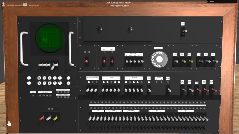
The Controls on the Console
The emulator console is based on the final 1956 Pilot ACE control panel as it appears in the Science Museum. Automatic Computing Engine (ACE) pilot model, 1949. Not all of the switches have been identified and some are assumed based on information from the DEUCE computer as this was a close copy of the Pilot ACE.
Scope Panel

At the top is the oscilloscope display which, going by the DEUCE's use, could display the contents of various delay lines. No exact description has yet been discovered as to exactly what was shown on the ACE, but the DEUCE showed a 0 in the delay line as a dim dot and a 1 as a bright dot, so that is how it is shown on this simulation.
The next row of 5 grey switches has no documented purpose, but on Virtual Pilot ACE (as on David Green's version), I've assumed that these are to control the scope display above. The delay line from 1 to 11 can be set in reverse binary on these switches. From left to right, they are counted as 1, 2, 4, 8 and 16 in value so to set to view delay line 10, you would set the 2 and 8 switches down. Setting switch 16 down displays the double and short delay line contents.
The two rows of white numerical buttons are next and again, there's no official documentation on these, but I have used these to set the specific values on the I.D. input. The numeric buttons 0-9 set the corresponding P1 - P10 lights on while the P1 and P32 set those lights directly.
The set of lamps shown (write, head number etc) are for the addition of a magnetic drum memory which was added in March 1954. This currently is not simulated on this version, but will be added at a later date.
The last three switches below are again unknown and are not described in any known documents I can find. The first two (red and grey) are unused in this simulation but the yellow one is used as the M.C. Slip which adjusts which microcycle the display begins displaying in. Each time this key is depressed down, the Delay Lines screens will move up 2 positions.
First Row

For the first row of the main panel, I've included the full top section. This included what I believe is a drawer and I have (for ease of use) shown the "Initial Input" switch in the top right. This, I believe, was actually on a panel on the card reader. The row of switches and oddly, a telephone dial, are described from left to right below. Any marked † have not yet been simulated in this initial version of Virtual Pilot ACE but should be in future versions.
Two neons and one key for which the purpose are unknown, the simulation ignores these.
Hollerith Read Key† : Key pressed - stimulate reader for one card. Key is spring-loaded and will revert to neutral (level) position. [If there is a program deck in the reader, cards will continue to be read all the while each card has a one punched in column 35 of row 9.]
Hollerith Punch Key† : Stimulate punch for one card - the Punch isn't yet implemented on this version of Pilot ACE.
Request Stop Keys† : The Request Stop facility will stop the computer on any instruction with particular NIS, Source or Destination or combination of these. To set these you would set one or more of the NIS, Source or Destination down along with the "Ext Tree" switch which activates the set of switches on the second row of the main panel. You could then set a specific pattern of NIS, Source or Destination values and the computer would stop on the next command that matched those parameters. To continue, the Ext Tree would be set back to normal.
DISC request stop† : This is assumed to be the same as the DEUCE where the computer will stop on a discrimination command. If set Down, it would stop on a 24 discriminate on sign command and if set Up, would stop on a discriminate on zero command
The final request stop key is known
The One Shot dial : This enabled an exact number (between 1 and 10) one-shots to be supplied to the computer by dialling as on an old telephone dial. To do this on Virtual Pilot ACE, click on the number you want to dial and drag it around clockwise to the stop, then release.
TIL† : The TIL is the Twelfth Impulse Line, while the key marked TIL is down, the TIL signal is given continuously. As each row of a punched card is read, it is useful for the computer to know when the final (twelfth) row of the card has completed, this is done via a signal called the TIL. This switch is currently not implemented on this version of Virtual Pilot ACE.
DISC† : This key forces a value for one of the discrimination branch destinations. Setting the key up forces a positive branch for D24 or a zero branch for D25; setting down, forces a negative branch for D24 or a non-zero branch for D25. Not currently implemented on Virtual Pilot ACE
Clear Store : This spring return key clears the delay line stores.
Cont T.C.I† : The TCI signal is normally applied for the one minor cycle in which Control is to take a new instruction, and allows an instruction to enter TS COUNT from the instruction highway or via destination 0. The signal is applied while the Timing key (marked TCI) is down. A stream of instructions enter TS COUNT, and the last instruction to enter TS COUNT before the key is raised stays in TS COUNT and is displayed on the IS lamps. Not currently implemented on Virtual Pilot ACE
Ext Tree† : While it is down the External Tree facility is operating. This facility allows NIS, Source, Destination and Characteristic of the instruction in TS COUNT to be ignored and the reading from 13 IS keys (the keys below the Instruction Staticiser lamps) and a characteristic key (labelled Char) to be taken instead. Not currently implemented on Virtual Pilot ACE.
Cont T.T.† : The transtim signal, which allows transfer to take place from Source to Destination specified by the instruction held in TS COUNT (or by External Tree when this is operative) is applied (for a number of complete mc's) while the Transtim key (marked CONT TT) is held down. Not currently implemented on Virtual Pilot ACE.
Second Row
The first set of neons and keys are the Instruction Staticiser. These give NIS, Source and Destination of the current instruction in TSCOUNT shown in reverse binary, mostly useful if the computer is stopped.

The switches below are active if the Ext Tree key above is set down†. This will override the value set to TSCOUNT to be run.
Triggers A / B : Two circuits in the computer modify the action of certain sources and destinations, these are the TCA and TCB. The TCA lamp is lit when TCA is on, likeiwse, the TCB lamp is let when TCB is on.
Buzzer† : The Pilot ACE could alert the operator by turning on an buzzer neon and sounding a buzzer. [For DEUCE, the buzzer key had three positions which worked as follows: Level was neutral; Down was spring-loaded - it turned off the buzzer and the buzzer neon; Up killed the buzzer but left the buzzer neon operating normally]. The buzzer is not emulated currently.
Spec Word : The 32 Special Word switches (the lowest row of black switches) provided a means of setting a standard pattern on the ID lamps. They could be fixed into a downward or upward positions and the Spec Word switch enters these values into the current I.D. Pushing this key down puts all the I.D values on where a Special Word switch is down while pushing this key up inverses that value.
Clear I.D. : Pushing this switch down (spring loaded) clears the current value on the input dynamiciser neons below. Setting it up continuously clears this value
Stop : When this is in the normal central position, the computer goes at it's own speed. If it encounters a Stopper command, it obeys it only when it receives a one-shot. When this is down, the computer interprets every instruction as a Stopper.
One shot : Pressing down the spring return one-shot key supplies a single shot. This continues a Stopper command.
Clear O.P.S. : The Output Staticicer neons (the top row of 32 neon bulbs below) can show a reverse binary value from the computer. The Pilot ACE only has options to light the neons, only this Clear O.P.S key will extinguish them to allow another number to be shown.
Input/Output Row
The final part of the console is the Input / Output neons and keys. These are known as the Input Dynamiciser (I.D.) and the Output Staticiser (O.P.S)

The top row of 32 neons show the O.P.S value. This is in reverse binary with the LSB on the left (rather than the now more normal right hand side LSB). Therefore the value 19 would be shown by lights on the left showing 11001 (1+2+16)
The second row of 32 neons show the I.D. value, again in reverse binary. To set a bit, you would use the corresponding grey switches below and press the key down. To clear the bit, press the corresponding key up.
The last row of 32 black switches are the Special Word. These keys are not spring loaded and can be fixed into an up or down state. Pressing the Spec Word key above will enter these set values (or their inverse) into the I.D. meaning a much used value can be set again and again without having to set each single key.
Other Reading
www.uraone.com/computers/pilotace David Green's Pilot ACE web page has a huge amount of information about Pilot ACE
https://web.archive.org/web/20161004032325/http://pilotaceonline.com/ David Green's Pilot ACE simulation for Windows is still available on the internet archive
alanturing.net AlanTuring.net has archived and released many historical documents from 1944 onwards for the Pilot ACE