The first Pilot ACE program, 10th May 1950. Successive Digits
or; How do you program a 1950s computer?
J.H Wilkinson wrote the following regarding the first program to be run on the new partially built Pilot ACE
"Towards the end of the day on 10th May 1950 we had all the basic pulse circuits working, the control unit, one long delay line and a short delay line fitted with an additive and subtractive input. However, our only method of inserting instructions was via a set of 32 switches on which we could set up one instruction at a time in binary; our only method of output was a set of 32 lights to which a binary number could be sent"
"Unfortunately the amplifier on the delay line was barely adequate and the probability of remembering a pulse pattern for as long as a minute was not very high. We concocted a very elementary program consisting of a few instructions only; this took the number on the input switches, added it into the short delay line once per millisecond and put on the next light on the set of 32 output lights when the accumulator overflowed. The lights therefore came on at a speed which depended on the size of the number on the input switches. We laboriously fed this program again and again into the computer but each time the memory would fail before we could finish. On about the twentieth occasion we finally succeeded in inserting the whole program and all the lights flashed up instantaneously. We reduced the input number and they came on slowly one by one; we doubled it and the lights came on at twice the rate and we switched off for the day knowing the computer was working. [WJ05 99]"
Donald Davies also is quoted as saying "The first Pilot ACE program became known as 'Suc Digs'. It was designed to test out the loading and operation of instructions, the single length accumulator TS16, input and output of a simple kind, both kinds of jump instruction and shifting in TS26. This simple program became the last resort when testing the machine after a failure. If it couldn't do 'Suc Digs', it was in a poor state, so 'Suc Digs' became an institution." [DD2].
As one of the simplest programs for the Pilot ACE, let's take a closer look at Suc. Digs and work through how you go about designing a program for the Pilot ACE and what exactly it does. Note that the original version of the program is unfortunately lost to time, but in 1999, Donald Davies recreated the code to the best of his knowledge "There was no record of the [code] we used on the real machine, but [my version of Suc. Digs.] does the same thing - as far as I can remember." [DD2]. This is the version we'll be looking into here (and the one that runs on the Virtual Pilot ACE simulator)
Creating a flow chart
Given the complexity of "Optimal Coding", preparing a program for Pilot ACE was no simple task. Therefore, it was customary to divide the programming task into two sections: Firstly, a flowchart of the operations was completed putting the commands to be run in order. Just the basic information was given here mostly the source and destination plus the delay line and mc each line was stored in. Secondly, a more detailed programming sheet was completed giving the final storage location and working out the wait and timing numbers.
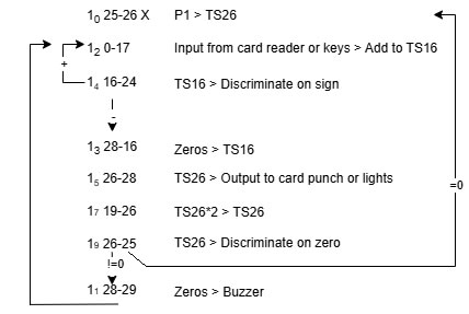
Shown here is the flowchart for Suc. Digs. You can see it's quite a simple program at just 8 lines long.
You may want to initially take a look at it running on Virtual Pilot ACE to see what it looks like for real. See here for instructions on how to do this first:
How to run Suc. Digs.
We'll take a look at each line in turn to see what it does. You may also want to have the Function List available to hand to see what sources and destinations we're talking about: Pilot ACE Function List.
Each line is in the following format; 10. The first number lists the Delay Line number we're storing in (1) with the current minor cycle (mc) location that we should find the command stored in subscript (0).
10 25-26 X : P1 - TS26
The start of our program where we're at mc 0 and the instruction is to be stored in delay line DL1.
The source is 25 which (if you look at the function list), is P1. This is the actual value of 1 in binary which we can use without having to store it specifically in the program somewhere. The destination is 26 which is delay line TS26.
Therefore, this command simply just stores the value 1 into TS26.
One last note on this command, it's listed with an X afterwards. This means we want this command to be a stopping one without a "Go" digit. This means the computer will pause on this command until the "one-shot" key is pressed on the console. Basically, a pause while we wait for user input.
12 0-17 : I.D. - Add to TS16
The first thing to note about our second command is that it's showing as being run in mc 2 rather than 1. This is because the Pilot ACE takes 2 mc to load and run a command so if the first is loaded from mc 0 and only runs in a single minor cycle, then the next command will have to be in the delay line 2 mc more than the first.
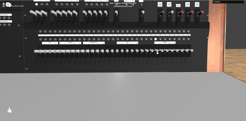
The command itself has a source of 0 which the function sheet shows as I.D. The I.D. is the fantastically named "Input Dynamiciser", which is basically the set of 32 hand operated switches where the operator can setup a single 32-bit binary number to be input. This is shown here on the right as the bottom set of grey switches and the lower row of lights.
The destination for this command is 17 which is TS16 add. This destination takes the source value and adds it to the existing value in the temporary store delay line TS16.
The full command is therefore take the value that's on the input switches and add it to the value in TS16
14 16-24 : TS16 - Discriminate on sign
This command (in mc4) is to take the value is TS16 and to "DISCRIMIATE on sign". There are two discriminate destinations which allow us to branch to another part of the program dependant on a specified value. Destination 24 checks if the source value supplied is positive or negative and will jump to either the next or next+1 instruction dependant on the result. In this case, we're running the command mc4 and if TS16 is positive, we want to loop back to mc2 (to add another value from the I.D. to TS16). Alternatively, if the value in TS16 is negative, then we'll end up at mc3 instead.
Basically, we're going to loop adding the value in I.D. to TS16 over and over again until we overflow the 32-bit value. The final 32nd bit of the stored word shows if the number is positive or negative, so eventually, the number in TS16 will switch from a positive one to a negative one once the binary number fills up completely.
13 28-16 : P0 - TS16
Source 28 is P0 (eg the value 0 in binary) and our destination is TS16, so here, we're simply just resetting the value in TS16 back to zero.
15 26-28 : TS26 - O.P.S
Note, that we're now in odd mc values so our next command is in mc5! The source for this command is TS26 and we're sending it to 28 which is "O.P.S". This is the Output Staticiser which is a fancy name for the 32 lights shown above the I.D. lights. Note that the O.P.S. lights do not clear when sent a value, each binary values sent to this output will light up bulbs where a 1 is in the binary, but will not extinguish those with a 0. The Clear O.P.S. key switch is the only way to clear down the O.P.S. lights. For our first time through our program loop, the value of TS26 is going to be 1.
An important note here about how the Pilot ACE shows and accepts binary numbers. All binary values on the Pilot ACE are in backwards binary which can be very confusing if you are used to our standard way of writing binary today with the least significant bit being on the right.
For example, the normal modern way of showing the binary number for decimal 13 would be 1101 (so 8+4+0+1), but on the Pilot ACE, the decimal number 13 would be written 1011! This means, that when we see the output of TS26 which is set to the value 1, it will light up the bulb on the far LEFT, not the right hand one!
17 19-26 : TS26*2 - TS26
Our next source is 19 which is TS26 x 2 and the destination is 26 which is TS26. So, we're multiplying the value of TS26 by 2 and storing it back into the same delay line. This is basically a bit shift, moving the values of all of the binary bits one to the right (remember we're in backwards binary). So we start with our binary value starting 1000 (decimal 1) and multiply it by 2 which gives a value 2, so 0100. If we were to run this command again, it would multiply 2 by 2 and give 4 which is 0010 etc.
19 26-25 : TS26 - Discriminate on zero
Now, we have our other discriminate command, DISCRIMINATE ON ZERO. Our source in this case is TS26 and we're checking if the value in this delay line is zero or not. If the value is 0, then we want to jump to the line in mc0, if it is not 0, then we want to jump to mc1 which jumps back to start adding up in the TS16 loop again. This is our main program loop and it's checking if the value we're showing on the O.P.S. lights has filled up completely and then reset back to 0. Once we've returned to zero, out program is completed, if it's not zero, we keep looping to add more lights.
11 28-29 : P0 - Buzzer
This is (I believe) just a dummy command to enable us to jump back to the beginning of the program. The actual command is source 28 which is P0 (the value of zero in binary) to 29, which is the buzzer! On the real Pilot ACE, the buzzer would activate if anything other than 0 was sent to it (to notify the operator that a program had finished for example). In this case, we're just sending a 0 there, so stop the buzzer (which we never started). This command will therefore do nothing, but will allow us to jump to another mc in the program - ie, back to the start command at mc0 and wait for user input.
Writing up the Programming Sheet
The next stage is to complete the Programming Sheet. We're going to store our program in DL1 and as our program is very short, there's plenty of room to keep it all within the one delay line. Larger programs would have the commands stored across multiple delay lines, simply setting the next NIS value of a command to tell the computer to retrieve the next command from a different delay line. With Optimal Coding, and to get the best out of our computer, we want to try to keep the Wait and Timing values down to as close to 0 as possible (especially in loops) so there's no delay running each command. Sometimes this means our program has to jump around all over the place!

To fill in the programming sheet, we just write in each of our commands into the correct mc against the delay line column. Our first line (25-26) we fill in on the mc0 line, the second command (0-17) on the mc2 line etc. As our program stays on DL1 only, we can fill in the NIS 1 value against each line.
Now we need to work out the Wait, Timing, Serial and Go values. Remember that the W (Wait) is the number of minor cycles to wait to run the command and the T (timing) is how long to run for and at what time to get the next command.
For our first command (25-26) at mc0, we want to simply run this just once and then pass onto the next command at mc2. This means we can just set our W to 0 and T to 0 which means run immediately (recall it takes 2mc to prepare and run a command). For this command, we also have a requirement to wait for user input, so we mark the Go value with an X to show we don't want this to automatically run
Next, we need to fill in the s (serial) command. If the serial digit was a 1, then the transfer would only ever run for a single minor cycle irrespective of the wait and timing fields. If 0, then the command would run repeatedly from time W until time T. Note that if the W and T values are both 0 or the same, the command will only run once anyway, irrespective of if we've set the serial option or not so we only really need to take this value into account where the Timing value has been set to 1 or more. As our first command has W and T as 0, we can ignore it and leave it at 0.
Our second command (0-17) at mc2 also just wants to run immediately, just once and to pass onto the next command at mc4, so again, we set W and T to 0, ignore the s and we want to run immediately, so leave the Go flag empty
The line for mc4 (16-24) is slightly different though, this is the TS16 - Discriminate on sign command. Looking at our flow chart, we want it to check on the sign of the value and if positive (discriminate is true), go to mc2 and if negative, go to the next line mc3.
Firstly, we want run our discriminate command as soon as we can (so at +2mc) so we can fill in our Wait command as 0. For the Timing, we want the next command to be at mc2 if true, so we need to wait for a total of 28mc to get to mc2. Where m is the current minor cycle, the next command time is calculated as m + 2 + T. This means that we load the command at mc4, it runs at mc6 then will wait for the timing value of 28 to load the next command. 4 + 2 + 28 = 34 modulo 32 = 2. For the serial digit, we set this to 1 to make sure we only run the discriminate the first time while waiting for the Timing of 28mc to pass. There's no point checking the value over and over again, it's not going to change!
Once we've completed the loop, the next commands at mc3, mc5 and mc7 all are just simply run immediately and jump straight to the next command in 2mc time, so all are just W=0, T=0.
In mc9, we have another discriminate command which we want to jump to mc0 where the value = 0 or to mc1 where the value != 0. Again, we can run immediately, so W=0 and we can again calculate m + 2 + T where m = 9 so we need to wait to 21mc to get to mc0 (modulo 32). Again, we can set the serial bit to 1, only run the once.
The final one to change is in mc1. We want to end up after the command has run at mc0 to start over waiting for the user to clear the O.P.S and select an I.D. switch. Therefore, we can set the T command to be 31 (1+2+31 mod 32 = 2)
PHEW!
Note how tricky it is to read this code back using just the final programming sheet or the final punched cards if you don't have the flow chart! You can't just read it sequentially, but have to work out which line is the next one to be read based on the W and T values. Glad we don't have to do this now!
Setting the Bootstrap code
You have have noticed the empty 4 lines above where our program is written on the coding sheet, these are for our bootstrap code. We need to have a way to tell the Pilot ACE to load all of the lines from the punched cards into the correct delay line ready to be run.
The designers came up with a clever method of loading the Pilot ACE programs in from punched cards! If you recall, the first source S0 was set to input from the I.D key switches, but it also was set to read in from the card reader! The way this worked is that the card reader was set to fire a single-shot control to the computer when a punched card was loaded and a row of holes ready in place to be read. This means that all we need to do to read a source from the punched cards is to set a source of 0 and then mark the command as a wait comamnd (Go X), this would then pause until the card was ready and in place to be read then automatically read in the value as the source.
The first destination 0 is also a special one, this destination injected an order into the instruction register directly. This means that setting a source and destination of a command to both be 0 and loading a card would transfer a row from the punched card into the instruction register and run it. If we have a switch that resets all of the Delay Lines (including the instruction register), calls a punched card into the reader and then waits (note that this is the default for an empty instruction register), then the first instruction from a card in the reader will automatically be run.
An initial input (a bootstrap) was created using 4 rows of code to be included as the first 4 lines on the punched card. The rest of the 32 instructions to fill an entire Delay Line would be set from rows 5 onwards giving a total of 3 cards (called a triad) as each punched card can hold 12 rows. Each set of 3 cards could load a single delay line, each triad including the initial 4 bootstrap lines which specified which delay line was to be filled. In this way, an entire program could be loaded onto multiple delay lines.
The basic bootstrap lines are shown as the first four lines here
                    1st row : 0 0 - 0    0  0 X

                    2nd row : X 0 - X   26 25 X

                    3rd row : X 0 - X s 30 31 X

                    4th row : 0 0 - X s 30 31 X

                    5th row : Instruction which is to occupy X0

                    6th row : Instruction which is to occupy X1

                    ...

                    36th row : Instruction which is to occupy X31


                    Where X is the D.L. to be filled
The details of how these lines work are a little complex. A more detailed description can be read in this document on AlanTuring.net (Programming and Coding for the Pilot Model ACE, by Wilkinson (46 pp.) 20 Nov 1951), see Chapter 18. Input of Instructions on pages 33 and 34. https://alanturing.net/turing_archive/archive/l/l13/l13.php
Preparing the Punched Cards
Each instruction is written onto the 80 columns of a punched card in the following format with the rest of the columns left blank. There are 12 rows per punched card and as discussed above, three cards fill a single long delay line
| N | S | D | s | W | T | X | ||||
| 1 | 3 | 5 | 5 | 1 | 1 | 5 | 3 | 5 | 2 | 1 |
N = next instruction source
S = source
D = destination
s = serial digit
W = wait number
T = timing number
X = go digit
not used.
Important note is that all of these values are written down in reverse binary, so 100 is the decimal value 1, not 4! There is another special hole is placed on the 35th column of the final row which tells the computer to automatically read another card in and continue after this one.
If you look at the listed punch card rows below, you can hopefully see the first four rows which are the bootstrap code from above loading into delay line 1 with the first line of the actual code starting on row 5.
Successive Digits0 000 00000 00000 00 00000 000 00000 000 00000000000000000000000000000000 0000000000000000 0 100 00000 10000 00 01011 000 10011 000 00000000000000000000000000000000 0000000000000000 0 100 00000 10000 10 01111 000 11111 000 00000000000000000000000000000000 0000000000000000 0 100 00000 10000 10 01111 000 11111 000 00000000000000000000000000000000 0000000000000000 0 100 10011 01011 00 00000 000 00000 000 00000000000000000000000000000000 0000000000000000 0 100 00111 10111 10 00000 000 11111 001 00000000000000000000000000000000 0000000000000000 0 100 00000 10001 00 00000 000 00000 001 00000000000000000000000000000000 0000000000000000 0 100 00111 00001 00 00000 000 00000 001 00000000000000000000000000000000 0000000000000000 0 100 00001 00011 10 00000 000 00111 001 00000000000000000000000000000000 0000000000000000 0 100 01011 00111 00 00000 000 00000 001 00000000000000000000000000000000 0000000000000000 0 000 00000 00000 00 00000 000 00000 000 00000000000000000000000000000000 0000000000000000 0 100 11001 01011 00 00000 000 00000 001 00100000000000000000000000000000 0000000000000000 0 000 00000 00000 00 00000 000 00000 000 00000000000000000000000000000000 0000000000000000 0 100 01011 10011 10 00000 000 10101 001 00000000000000000000000000000000 0000000000000000 0 000 00000 00000 00 00000 000 00000 000 00000000000000000000000000000000 0000000000000000 0 000 00000 00000 00 00000 000 00000 000 00000000000000000000000000000000 0000000000000000 0 000 00000 00000 00 00000 000 00000 000 00000000000000000000000000000000 0000000000000000 0 000 00000 00000 00 00000 000 00000 000 00000000000000000000000000000000 0000000000000000 0 000 00000 00000 00 00000 000 00000 000 00000000000000000000000000000000 0000000000000000 0 000 00000 00000 00 00000 000 00000 000 00000000000000000000000000000000 0000000000000000 0 000 00000 00000 00 00000 000 00000 000 00000000000000000000000000000000 0000000000000000 0 000 00000 00000 00 00000 000 00000 000 00000000000000000000000000000000 0000000000000000 0 000 00000 00000 00 00000 000 00000 000 00000000000000000000000000000000 0000000000000000 0 000 00000 00000 00 00000 000 00000 000 00100000000000000000000000000000 0000000000000000 0 000 00000 00000 00 00000 000 00000 000 00000000000000000000000000000000 0000000000000000 0 000 00000 00000 00 00000 000 00000 000 00000000000000000000000000000000 0000000000000000 0 000 00000 00000 00 00000 000 00000 000 00000000000000000000000000000000 0000000000000000 0 000 00000 00000 00 00000 000 00000 000 00000000000000000000000000000000 0000000000000000 0 000 00000 00000 00 00000 000 00000 000 00000000000000000000000000000000 0000000000000000 0 000 00000 00000 00 00000 000 00000 000 00000000000000000000000000000000 0000000000000000 0 000 00000 00000 00 00000 000 00000 000 00000000000000000000000000000000 0000000000000000 0 000 00000 00000 00 00000 000 00000 000 00000000000000000000000000000000 0000000000000000 0 000 00000 00000 00 00000 000 00000 000 00000000000000000000000000000000 0000000000000000 0 000 00000 00000 00 00000 000 00000 000 00000000000000000000000000000000 0000000000000000 0 000 00000 00000 00 00000 000 00000 000 00000000000000000000000000000000 0000000000000000 0 000 00000 00000 00 00000 000 00000 000 00000000000000000000000000000000 0000000000000000
One more card was sometimes added to the beginning of the card pack which was the "initial card". The minor cycles within a delay line were classified as odd or even and when the machine was started, there was an equal likelyhood of the first line being added to either odd or even lines. Some calculations (eg Multiplication or double-length arithmetic), required the program be in a specific odd or even cycle so it was important to make sure that the Pilot ACE was in one or the other on startup. This was what the initial card did.
Initial Card0 000 00000 11101 00 00000 000 00000 000 00000000000000000000000000000000 0000000000000000 0 000 00000 00000 00 00000 000 00000 000 00000000000000000000000000000000 0000000000000000 0 000 10111 01110 00 00000 000 10000 000 00000000000000000000000000000000 0000000000000000 0 000 00000 00000 00 00000 000 00000 000 00000000000000000000000000000000 0000000000000000 0 000 10011 10110 00 00000 000 00000 000 00000000000000000000000000000000 0000000000000000 0 000 00000 00000 00 00000 000 00000 000 00000000000000000000000000000000 0000000000000000 0 000 01110 10011 00 00000 000 10000 000 00000000000000000000000000000000 0000000000000000 0 000 00000 00000 00 00000 000 00000 000 00000000000000000000000000000000 0000000000000000 0 000 00000 10101 00 00000 000 10000 000 00000000000000000000000000000000 0000000000000000 0 000 00000 00000 00 00000 000 00000 000 00000000000000000000000000000000 0000000000000000 0 000 00111 01110 00 00000 000 01000 000 00000000000000000000000000000000 0000000000000000 0 000 00000 00000 00 00000 000 00000 000 00100000000000000000000000000000 0000000000000000
Several subroutine packs were later made available as a library (for example to do division or a particular multiplication function) and could be duplicated and added to your program as required.